
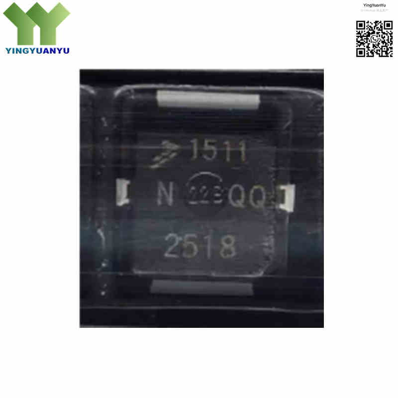
MRF1511NT1
| Part Number | MRF1511NT1 |
|---|---|
| Manufacturer | NXP Semiconductors / Freescale |
| Category | Discrete Semiconductor Products > Transistors > FETs, MOSFETs > RF MOSFETs |
| Description | N‑Channel RF Power LDMOS, 8W Power Output, Wide‑band VHF/UHF up to 175 MHz, 7.5V / 12.5V Operation, Surface Mount PLD‑1.5 Package, Obsolete EOL part. |
| Stock Status | In Stock |
| Origin | Original Factory |
Product Overview
MRF1511NT1 is NXP(Freescale) N‑channel LDMOS RF power transistor for VHF/UHF broadband amplifiers up to 175 MHz. Operating at 7.5‑12.5 V, it delivers 8 W output power with high efficiency. Packaged in PLD‑1.5 SMD housing, it features excellent VSWR ruggedness. This EOL obsolete device is mainly used for legacy radio equipment maintenance and replacement.
Core Advantages
High Gain & Efficiency
11.5‑13 dB gain, typical 70% drain efficiency, ideal for battery‑powered portable radios.
Low‑Voltage Operation
Optimized for 7.5‑12.5 V supply, matches land mobile radio system requirements.
Strong Mismatch Ruggedness
Resists antenna VSWR mismatch damage, improving field‑application reliability.
Compact SMD Package
PLD‑1.5 surface‑mount package supports SMT assembly and compact PCB layout.
Key Specifications
| Brand | NXP Semiconductors / Freescale |
|---|---|
| RoHS Status | Compliant with RoHS 3; early batches may differ by lot code |
| EDA/CAD | Symbol, Footprint & 3D Model Available |
| Warranty | 1‑Year Standard Quality Warranty |
| Package / Case | PLD‑1.5 (SOT‑4651 / CASE 466‑03) |
| Mounting Type | Surface Mount Device (SMD/SMT) |
| Surface Marking / Silkscreen | 1511N Marking |
| Transistor Type | RF LDMOS N‑Channel MOSFET |
| Frequency Range | Wide‑band VHF / UHF, Up to 175 MHz |
| Output Power Pout | 8.0 W (@7.5V,175MHz) |
| Power Gain Gp | Typ. 11.5 dB to 13 dB (at 175 MHz) |
| Drain Efficiency | Typ approx 70% |
| Quiescent Current IDQ | 150 mA (test condition) |
| Threshold Voltage VGS(th) | 1.0‑2.1 V, Typ 1.6 V |
| Input Capacitance Ciss | ≤100 pF @ 1 MHz, VDS=7.5V |
| Output Capacitance Coss | ≤53 pF @ 1 MHz, VDS=7.5V |
| Reverse Transfer Capacitance Crss | ≤8 pF @ 1 MHz, VDS=7.5V |
| Zero‑Gate‑Voltage Drain Current IDSS | ≤1 μA @ VDS=35V |
| Drain‑Source Voltage VDSS | 40 V DC Max |
| Gate‑Source Voltage VGS | ±20 V DC Max |
| Drain Operating Voltage VDD | 7.5 V to 12.5 V DC Nominal |
| Operating Temperature | -55℃ ~ +125℃ |
| Storage Temperature | -65℃ ~ +150℃ |
| Packaging Format | Tape & Reel (“T1” suffix denotes 7‑inch Tape & Reel) |
| Lifecycle Status | Obsolete(EOL), Last order date approx Apr 2020 |
Typical Applications
- VHF handheld land mobile radios (LMR) and commercial walkie‑talkies
- Automotive fleet communications, emergency service radios, and public safety transceivers
- VHF marine radio communication systems and coastal transceivers
- RF driver stages in higher‑power base stations and repeater systems
- Wireless telemetry systems and ISM band transmitters operating in the VHF range
- Maintenance & spare‑part replacement for legacy RF amplifier equipment
Order & Shipping Info
| Minimum Order Quantity (MOQ) | 1 Piece |
|---|---|
| Shipping Time | Shipped within 1‑2 business days |
| Delivery Time | 3‑7 working days worldwide |
| Shipping Methods | DHL, UPS, FedEx, EMS |
| Payment Methods | T/T (Bank Transfer), PayPal, Credit Card, Western Union |
Technical Support
For datasheet, sample requests, stock check, or bulk pricing, please use the Quick Inquiry form. We will reply within 24 hours.
Frequently Asked Questions
Q1: What does the “NT1” suffix mean in MRF1511NT1?
A: “N” refers to lead‑free revised version. “T1” stands for 7‑inch tape‑and‑reel for SMT assembly. Tray‑packed variants are available for this series.
Q2: What frequency does MRF1511NT1 support?
A: Designed for broadband VHF/UHF, maximum operating frequency up to 175 MHz, mainly for land mobile radio systems.
Q3: Can MRF1511NT1 directly replace MRF1508T1?
A: Both are 8 W PLD‑1.5 LDMOS, but not pin‑to‑pin drop‑in replacements. MRF1511NT1 is for VHF up to 175 MHz; MRF1508T1 targets UHF up to 520 MHz, with different internal matching circuits.
Q4: Is MRF1511NT1 still in production?
A: This part is obsolete (EOL). NXP last‑order date was April 2020. Our stock is original surplus for repair and legacy‑equipment replacement; not recommended for new designs.
Q5: Are there pin‑compatible drop‑in alternatives?
A: No fully direct drop‑in substitute. Submit an inquiry with your frequency, supply voltage and output‑power requirements, we can recommend suitable candidate parts for reference.
Q6: How to get datasheet, circuit schematic or bulk price?
A: Send your request via inquiry form. Our RF support team will return datasheet, stock confirmation and quotation within 24 hours.
Related Products

