
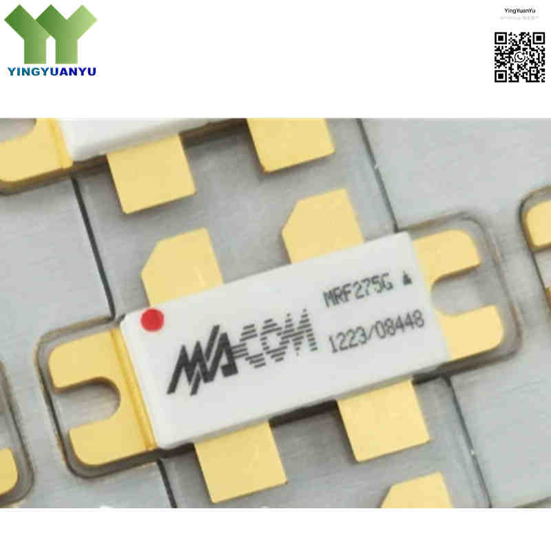
MRF275G
| Part Number | MRF275G |
|---|---|
| Manufacturer | M/A‑COM Technology Solutions / Motorola |
| Category | Discrete Semiconductor Products > Transistors – FETs, MOSFETs – RF |
| Description | 150W Push‑Pull N‑Channel Enhancement‑Mode RF Power MOSFET Transistor, 28V, 2 MHz to 500 MHz, Hermetic Flange Package. |
| Stock Status | In Stock |
| Origin | Original Factory |
Product Overview
The MRF275G is a dual N‑channel push‑pull RF power MOSFET by Motorola / MACOM for 2‑500 MHz. Powered by 28V DC, it outputs 150W CW @500MHz and 200W CW @225MHz. This hermetic flange‑mount device offers excellent thermal performance, low IMD and high VSWR tolerance for commercial, industrial and military VHF/UHF transmitters.
Core Advantages
Broadband RF Performance
2‑500 MHz bandwidth; 13 dB typical gain @225 MHz, 10 dB min gain @500 MHz for VHF/UHF transmitters.
Push‑Pull Dual‑die Structure
Pre‑matched dual dice, suppresses even harmonics and simplifies matching network design.
Superior Ruggedness
30:1 VSWR withstand capability. Negative temperature coefficient prevents thermal runaway, 400W total power dissipation @25°C.
Low‑Distortion Operation
Low intermodulation distortion, fits Class A, AB and C RF power amplifier applications.
Key Specifications
| Brand | MACOM / Motorola |
|---|---|
| RoHS Status | Non‑RoHS, Hermetic metal‑ceramic package |
| EDA / CAD | PCB Footprint & 3D Model Available upon Request |
| Warranty | 1‑Year Standard Quality Warranty |
| Package / Case | Case 375‑04 (Flange / Header Mount, Push‑Pull Style) |
| Mounting Type | Chassis / Flange Mount |
| Surface Marking / Silkscreen | MRF275G / MACOM |
| Transistor Technology | Dual N‑Channel RF Power MOSFET (Push‑Pull) |
| Frequency Range | 2 MHz to 500 MHz |
| Output Power (Pout) | 150 W CW @500MHz,28V; 200W CW @225MHz,28V |
| Power Gain (Gps) | 13 dB (Typ @225 MHz,28V); 10dB Min /11.2dB Typ @500MHz,28V |
| Drain‑Source Voltage (VDS) | 65 V (Max) / 28 V (Nominal Operating) |
| Gate‑Source Voltage (VGS) | ±40 V (Max) |
| Drain Current (ID) | 26 A (Max total) |
| Total Power Dissipation(Pd) | 400 W @ 25°C |
| Thermal Resistance (θjc) | 0.44 °C/W |
| Input Capacitance(Ciss) | 135 pF (Typ) |
| Output Capacitance(Coss) | 140 pF (Typ) |
| Reverse Transfer Capacitance(Crss) | 17 pF (Typ) |
| Operating Junction Temperature | -65°C to +150°C |
Typical Applications
- VHF and UHF Commercial, Tactical, and Military Radio Communications
- FM Broadcast Amplifiers, TV Transmitters, and Repeaters
- Class A, Class AB, and Class C High‑Power RF Linear Amplifiers
- Industrial, Scientific, and Medical (ISM) RF Generators and Plasma Equipment
- Avionics Communications and Mobile Broadband Power Drivers
Order & Shipping Info
| Minimum Order Quantity (MOQ) | 1 Piece |
|---|---|
| Shipping Time | Shipped within 1‑2 business days |
| Delivery Time | 3‑7 working days worldwide |
| Shipping Methods | DHL, UPS, FedEx, EMS |
| Payment Methods | T/T (Bank Transfer), PayPal, Credit Card, Western Union |
Technical Support
For datasheet, sample requests, stock check, or bulk pricing, please use the Quick Inquiry form. We will reply within 24 hours.
Frequently Asked Questions
Q1: What is the operating frequency and power rating of the MRF275G?
A: It works from 2‑500 MHz. Delivers 150W CW @500MHz and 200W CW @225MHz at 28V supply; typical gain 13dB @225MHz, minimum 10dB @500MHz.
Q2: What transistor topology does the MRF275G utilize?
A: It is dual N‑channel push‑pull RF MOSFET with matched internal dice inside hermetic flange package. Designed for push‑pull amplifiers, not fit for single‑ended circuits.
Q3: What is the nominal supply voltage for the MRF275G?
A: Nominal operating voltage is 28V DC, maximum VDS rating is 65V.
Q4: What is the difference between MRF275 and MRF275G?
A: Pin‑to‑pin compatible with same electrical specs. MRF275 is non‑hermetic for commercial indoor use. MRF275G is hermetic metal‑ceramic package for military and harsh environments with better vibration & moisture resistance.
Q5: Can MRF275G be directly replaced by MRF275L?
A: Not a direct replacement. MRF275G is dual‑die push‑pull device; MRF275L is single‑ended MOSFET. Pinout, internal structure and application circuits differ.
Q6: What does suffix “G” stand for in MRF275G?
A: Suffix G means hermetic metal‑ceramic sealed flange package for high‑shock, high‑humidity field conditions.
Q7: Are there alternative compatible push‑pull RF MOSFET options for MRF275G?
A: MRF275 is pin‑compatible non‑hermetic alternative. No direct single‑ended drop‑in substitute. Verify package, push‑pull structure and 28V rating before cross‑reference replacement.
Q8: How can I request official datasheets, pinout diagrams, or volume pricing for MRF275G?
A: Datasheets, footprint info and bulk quotes can be requested via our Quick Inquiry form.
Related Products

