
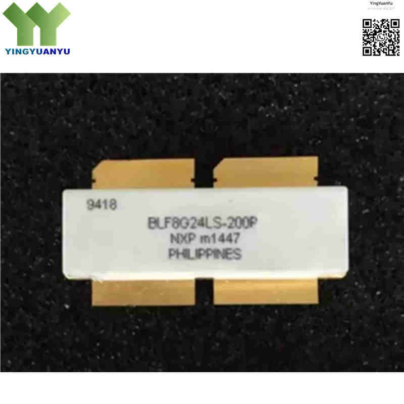
BLF8G24LS-200P
| Part Number | BLF8G24LS-200P |
|---|---|
| Manufacturer | Ampleon / NXP Semiconductors |
| Category | Discrete Semiconductor Products > Transistors – FETs, MOSFETs – RF |
| Description | Power LDMOS Transistor, 200W CW (3‑dB compression), Push‑Pull, 2300 MHz to 2400 MHz, 28V, SOT539B Package. |
| Stock Status | In Stock |
| Origin | Original Factory |
Product Overview
The BLF8G24LS‑200P is a high‑power push‑pull LDMOS RF transistor from Ampleon (formerly NXP). Optimized for 2300‑2400 MHz base‑station applications. It delivers 200 W CW at 3‑dB compression and 60 W average power under single‑carrier W‑CDMA modulation at 28 V supply. Built on Gen8 LDMOS process, it offers high gain, good ruggedness and low thermal resistance in SOT539B earless ceramic package, ideal for Doherty and multi‑carrier LTE power amplifiers.
Core Advantages
Push‑Pull High Power Density
Dual‑path push‑pull topology delivers 200 W peak RF power with compact footprint.
High Efficiency & Gain
Gen8 LDMOS technology provides high gain and efficiency to reduce power consumption and cooling demand.
Integrated Matching Networks
Built‑in input/output matching simplifies circuit design and cuts external components.
High Ruggedness & Low Thermal Resistance
Withstands 10:1 all‑phase VSWR; SOT539B ceramic flange package ensures excellent heat dissipation.
Key Specifications
| Brand | Ampleon / NXP Semiconductors |
|---|---|
| RoHS Status | RoHS Compliant / Lead‑Free |
| EDA / CAD | PCB Footprint & 3D Model Available upon Request |
| Warranty | 1‑Year Standard Quality Warranty |
| Package / Case | SOT539B (Earless Ceramic Flange, 4‑pin) |
| Mounting Type | Chassis Mount / Flange Mount |
| Surface Marking / Silkscreen | BLF8G24LS‑200P Marking |
| Transistor Type | LDMOS N‑Channel RF Power Transistor (Push‑Pull) |
| Operating Frequency Range | 2300 MHz to 2400 MHz |
| Output Power (Pout) | 200 W CW @3‑dB compression; 60 W average (1‑carrier W‑CDMA) |
| Drain‑Source Voltage (Vds) | 28 V DC Typ. (Max 65V Vdss) |
| Power Gain (Gps) | 17.2 dB Typ. (Min 15.8 dB) @ 2350 MHz |
| Drain Efficiency | 32% Typ. (1‑carrier W‑CDMA condition) |
| Thermal Resistance Rth(j‑c) | 0.217 K/W Typical |
| IDq Quiescent Current | 1740 mA (dual‑unit total) |
| Max Junction Temperature | 150 °C |
| Storage Temperature | -65 °C to +150 °C |
| VSWR Ruggedness | Survives 10:1 VSWR all‑phase at 28V, 200W CW |
| Adjacent Channel Power Ratio (ACPR) | -37 dBc Typ. @5 MHz offset |
Typical Applications
- LTE, WiMAX, and W‑CDMA Wireless Base Station Power Amplifiers (2.3 GHz ‑ 2.4 GHz Band)
- High‑Efficiency Doherty Power Amplifier Architectures
- Macrocell Base Station Multi‑Carrier Power Amplifiers (MCPA)
- Cellular Repeater Systems and Small Cell Transmission Equipment
- Industrial, Scientific, and Medical (ISM) 2.4 GHz RF Power Applications
Order & Shipping Info
| Minimum Order Quantity (MOQ) | 1 Piece |
|---|---|
| Shipping Time | Shipped within 1‑2 business days |
| Delivery Time | 3‑7 working days worldwide |
| Shipping Methods | DHL, UPS, FedEx, EMS |
| Payment Methods | T/T (Bank Transfer), PayPal, Credit Card, Western Union |
Technical Support
For datasheet, sample requests, stock check, or bulk pricing, please use the Quick Inquiry form. We will reply within 24 hours.
Frequently Asked Questions
Q1: What operating frequency range is supported by the BLF8G24LS‑200P?
A: Optimized for wireless infrastructure, operating within 2300 MHz‑2400 MHz band.
Q2: What does the ‘P’ suffix stand for in part number?
A: The “P” indicates internal push‑pull dual‑path configuration inside one package.
Q3: What package is BLF8G24LS‑200P?
A: Earless ceramic SOT539B 4‑pin flange‑mount package. Pins: Drain1, Drain2, Gate1, Gate2; source connected to flange.
Q4: How to get datasheet, S‑params or volume pricing?
A: Submit inquiry via our Quick Inquiry form for datasheets, S‑parameter files, stock status and bulk quotations.
Q5: What is difference between BLF8G24LS‑200P and BLF8G24LS‑200PN?
A: They share identical die, package and electrical specifications. Suffix PN is an ordering‑code for different packaging / distributor‑specific order part number, no hardware change.
Q6: What are compatible & alternative replacement parts?
A: Pin‑to‑pin compatible: BLF8G24LS‑200P‑112, BLF8G24LS‑200P‑118.
Single‑ended alternative: BLF8G24LS‑100 (100W, not push‑pull, circuit redesign required).
Higher‑power option: BLF8G24LS‑300P (300W push‑pull SOT539B).
Q7: What are competitor alternatives?
A: Infineon PT220240V200, Mitsubishi RD24HVS‑200. These are NOT pin‑compatible, RF matching network needs full redesign.
Q8: What is difference between CW power and average power?
A: 200 W CW = 3‑dB compression sine‑wave test power. 60 W average = real‑world output under single‑carrier W‑CDMA modulation for base‑station amplifiers.
Q9: Can this transistor work in Doherty PA designs?
A: Yes. Low output capacitance and low memory effect make it well‑suited for Doherty architecture to boost overall system efficiency.
Q10: What is the VSWR ruggedness rating?
A: Survives 10:1 VSWR all‑phase at 28 V supply and 200 W CW output, suitable for harsh field base‑station environments.
Q11: What is recommended operating voltage and IDq bias?
A: Typical drain supply Vds = 28 V. Quiescent current IDq = 1740 mA for dual‑unit total. Max Vdss rating is 65 V, do not exceed this absolute maximum rating.
Related Products

