
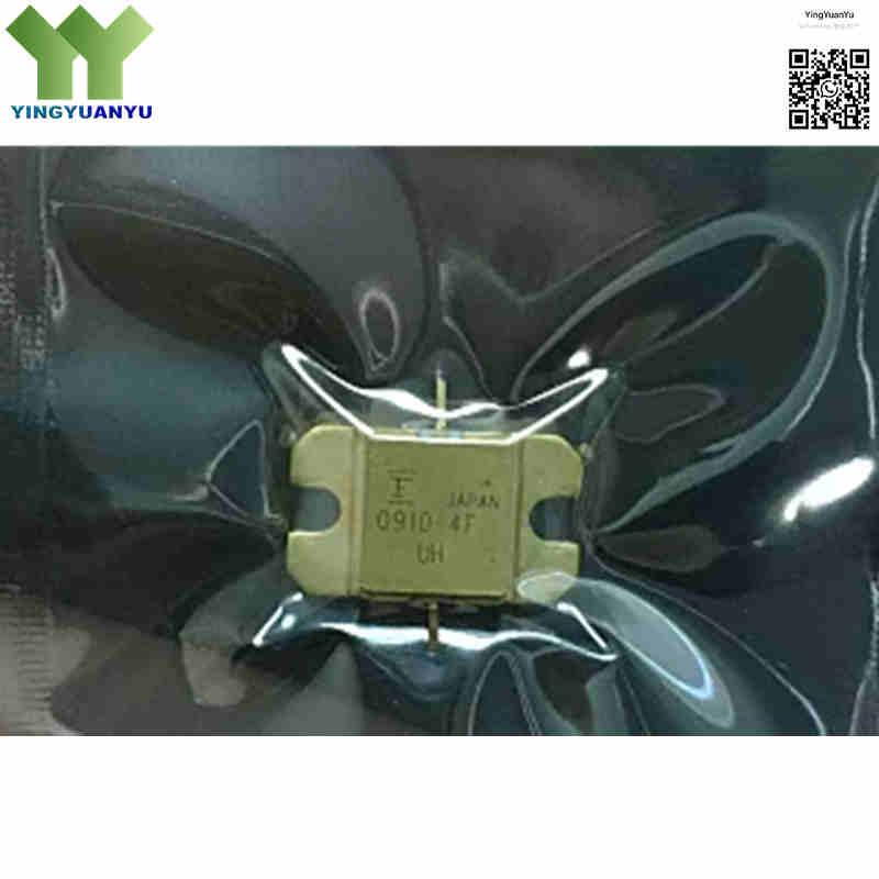
FLM0910-4F
| Part Number | FLM0910-4F |
|---|---|
| Manufacturer | Eudyna Devices / Fujitsu / Sumitomo Electric (SEDI) |
| Category | Discrete Semiconductor Products > Transistors – FETs, MOSFETs – RF |
| Description | Internally Matched X‑Band Power GaAs FET, 4W Output Power, 9.5 GHz to 10.5 GHz, Flanged Hermetic Ceramic Package. |
| Stock Status | In Stock |
| Origin | Original Factory |
Product Overview
The FLM0910‑4F is an internally matched power GaAs FET by Eudyna (Sumitomo SEDI) for X‑band microwave power amplification. It delivers typical 4W (36dBm) P1dB output power at 9.5‑10.5 GHz, with built‑in 50‑ohm input‑output matching to simplify PCB layout. Housed in hermetic IB metal‑ceramic flange package for chassis‑mount heat dissipation, suitable for SATCOM, radar and defense microwave systems.
Core Advantages
Internal 50‑Ohm Matching Circuits
Integrated input‑output matching networks, removes external tuning components and shortens RF product development cycle.
High Output Power & Linear Gain in X‑Band
Typical 4W P1dB output power, 7.0dB gain across 9.5‑10.5 GHz for X‑band power amplifier designs.
Proven High‑Reliability GaAs Process
Gold‑metallized GaAs Schottky‑gate technology, low IMD3 distortion, stable performance under high RF drive.
Hermetic Flanged Ceramic Package
IB hermetic metal‑ceramic flange package for direct chassis heatsink mounting, low thermal resistance for long‑term reliable operation.
Key Specifications
| Brand | Eudyna / Fujitsu / Sumitomo Electric (SEDI) |
|---|---|
| RoHS Status | RoHS Compliant Options Available |
| EDA / CAD | PCB Footprint & 3D Model Available upon Request |
| Warranty | 1‑Year Standard Quality Warranty |
| Package / Case | IB Package (Hermetic Metal‑Ceramic Flange) |
| Mounting Type | Chassis Mount / Flange Mount |
| Surface Marking / Silkscreen | 0910‑4F |
| Transistor Type | RF Power GaAs FET |
| Frequency Range | 9.5 GHz to 10.5 GHz (X‑Band) |
| Output Power (P1dB) | 4 W (36 dBm Typical) |
| Power Gain (G1dB) | 7.0 dB (Typical) |
| Operating Drain Voltage (VDS) | 10 V (Nominal) |
| Impedance | 50 Ω Internally Matched (In/Out) |
| Power‑Added Efficiency (PAE) | 29% (Typical) |
| Drain Current (Idq) | 1100‑1300 mA (Typical) |
| Thermal Resistance (RθJC) | 12 ℃/W (Max) |
| Operating Channel Temperature | ‑55°C ~ +175°C |
| Storage Temperature Range | ‑65°C ~ +175°C |
| 3rd‑Order Intermodulation (IM3) | ‑46 dBc Typical |
Typical Applications
- X‑Band Satellite Communication (SATCOM) Earth Stations and VSAT Systems
- Point‑to‑Point High‑Capacity Microwave Digital Radio Links
- Commercial and Military X‑Band Radar Transceivers and Search Radars
- Electronic Warfare (EW) Signal Amplification and Missile Guidance Radar Systems
- High‑Power RF Test & Measurement Equipment and Signal Drivers
Order & Shipping Info
| Minimum Order Quantity (MOQ) | 1 Piece |
|---|---|
| Shipping Time | Shipped within 1‑2 business days |
| Delivery Time | 3‑7 working days worldwide |
| Shipping Methods | DHL, UPS, FedEx, EMS |
| Payment Methods | T/T (Bank Transfer), PayPal, Credit Card, Western Union |
Technical Support
For datasheet, sample requests, stock check, or bulk pricing, please use the Quick Inquiry form. We will reply within 24 hours.
Frequently Asked Questions
Q1: What is the primary operating frequency band and power rating of FLM0910‑4F?
A: Operates X‑band 9.5‑10.5 GHz, typical P1dB output power 4W (36dBm), typical gain 7.0dB at Vds=10V.
Q2: Does the FLM0910‑4F require external RF matching networks?
A: No, input and output are pre‑matched to 50Ω internally, no extra external matching components required.
Q3: What does the suffix “‑F” stand for in FLM0910‑4F?
A: “‑F” means IB flanged hermetic package for chassis heatsink mounting. Non‑F versions use different mechanical housing, electrical specs differ accordingly.
Q4: Are there pin‑compatible alternative parts within FLM0910 family?
A: FLM0910 series share similar X‑band architecture: FLM0910‑3F(3W), FLM0910‑4F(4W), FLM0910‑8F(8W), FLM0910‑12F(12W). Same IB flange package, different output power. Not direct drop‑in, verify bias and power supply before replacement.
Q5: What are package and mounting restrictions?
A: IB hermetic flange package, must use chassis‑flange mounting for heat dissipation. Not compatible with SMT reflow soldering.
Q6: What is operating and storage temperature range?
A: Operating channel temperature: ‑55℃ ~ +175℃; Storage temperature: ‑65℃ ~ +175℃.
Q7: How can I request official datasheets, S‑parameter files, or volume price quotes for FLM0910‑4F?
A: Submit Quick Inquiry form to get official datasheet, S‑parameter, stock status and bulk quotation.
Related Products

