
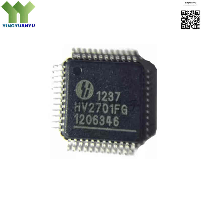
HV2701FG-G
| Part Number | HV2701FG-G |
|---|---|
| Manufacturer | Microchip Technology / Supertex |
| Category | Integrated Circuits (ICs) > Interface – Analog Switches, Multiplexers, Demultiplexers |
| Description | Low-parasitic, 16-channel high-voltage analog switch IC with built-in bleed resistors 26Ω, supports ±100V analog signal switching for medical ultrasound equipment, 48-lead LQFP package. |
| Stock Status | In Stock |
| Origin | Original Factory |
Product Overview
The HV2701FG-G is a 16-channel high-voltage analog switch IC from Microchip for medical ultrasound and industrial flaw detection equipment. It adopts high-voltage CMOS technology supporting ±100V analog signals, featuring low on-resistance and low parasitic capacitance. Each channel integrates bleed resistors to eliminate transducer residual charge noise. Equipped with serial shift register control, it easily connects with FPGA/MCU, and the 48-LQFP 7×7mm lead-free package saves PCB space for multi-channel probe equipment.
Core Advantages
16-Channel High-Density Integration
16 independent high-voltage switches in one chip, simplifying PCB layout and cutting multi-channel device BOM costs.
Built-in Bleed Resistor Network
On-channel bleed resistors quickly release transducer residual voltage, preventing equipment damage and signal noise.
Excellent Signal Integrity & Low Distortion
Low on-resistance and tiny parasitic capacitance reduce crosstalk and waveform distortion during high-frequency pulse transmission.
Wide High-Voltage Input Range
Supports ±100V analog rail, compatible with all mainstream ultrasonic piezoelectric drive circuits.
Key Specifications
| Brand Series | Microchip Supertex High-Voltage Ultrasound Analog Switch |
|---|---|
| RoHS Status | RoHS Compliant, Lead-free, Halogen-free; “-G” suffix stands for green environmental standard |
| EDA Models | Schematic symbol, PCB footprint and 3D STEP model available on request |
| Quality Warranty | 1-year original factory quality warranty |
| Package / Case | 48-LQFP 7mm × 7mm |
| Mounting Type | SMT surface mount, compatible with lead-free reflow soldering |
| Device Marking | HV2701FG Marking |
| Channel Count | 16 independent high-voltage analog switch channels |
| Analog Signal Voltage | ±100V maximum analog signal range |
| Typical On Resistance(Ron) | 26Ω under standard operating voltage |
| Channel Output Capacitance | 38pF typical channel capacitance |
| Built-in Bleed Resistor | 35kΩ minimum bleed resistor per channel output |
| Logic Input Voltage | 3V ~ 5.5V CMOS logic signal compatible |
| Max Serial Clock Frequency | 20MHz maximum shift register clock rate |
| Switching Time | Turn-on & Turn-off time ≤5μs |
| Operating Temperature | 0°C ~ +70°C commercial temperature range |
| Application Scenarios | Medical ultrasound imaging, piezoelectric transducer drive, industrial NDT flaw detection |
Typical Applications
- Medical B-mode & Color Doppler Ultrasound Diagnostic Equipment
- Piezoelectric transducer multiplexer and ultrasound probe circuit
- Industrial NDT ultrasonic flaw detection equipment
- Multi-channel hydrophone and acoustic array equipment
- High voltage ATE test matrix signal switching system
Order & Shipping Info
| Minimum Order Quantity (MOQ) | 1 Piece |
|---|---|
| Processing Time | Ship out within 1-2 working days |
| Global Transit Time | 3-7 working days |
| Shipping Carriers | DHL, UPS, FedEx, EMS |
| Payment Terms | T/T Bank Transfer, PayPal, Credit Card, Western Union |
Technical Support
Send inquiry via our contact form for datasheet, free samples, stock quantity and bulk quotation. We will reply within 24 hours.
Frequently Asked Questions
Q1: Are HV2701FG-G parts original new stock?
A1: 100% brand new original Microchip parts. Stored in vacuum anti-static moisture-proof bags to avoid ESD damage and guarantee stable SMT performance.
Q2: What do FG and -G suffix mean?
A2: FG stands for 48-lead 7×7mm LQFP package; suffix -G means lead-free, halogen-free and fully RoHS compliant.
Q3: What is the function of built-in bleed resistors?
A3: It quickly releases residual voltage on piezoelectric transducers, eliminates image noise and bright spots to improve ultrasound imaging quality.
Q4: How to avoid CMOS latch-up damage?
A4: Power on logic VDD first, then ±100V high voltage rail; reverse the order when powering off. Contact us for PCB layout reference.
Q5: Can I get free samples of HV2701FG-G?
A5: Yes, free samples are available. Just submit a sample request via our contact form with your quantity and application info.
Q6: What’s your minimum order quantity?
A6: Small sample orders are acceptable. Better unit price for bulk orders above 30pcs.
Q7: How long is your delivery lead time?
A7: In-stock items ship within 1-3 working days; out-of-stock bulk orders take 2-4 weeks.
Q8: Do you provide datasheet and technical schematic support?
A8: Sure, official datasheets, circuit reference and PCB layout files will be sent with your inquiry.
Related Products

