
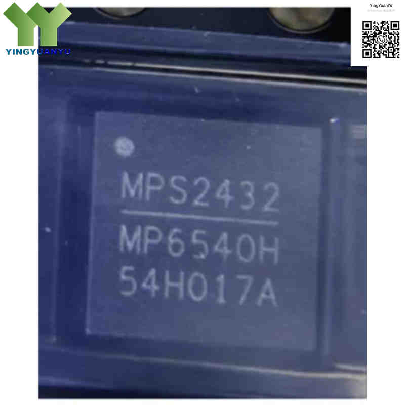
MP6540HGU-Z
| Part Number | MP6540HGU-Z |
|---|---|
| Manufacturer | Monolithic Power Systems (MPS) |
| Category | Integrated Circuits (ICs) > Power Management (PMIC) > Motor Drivers, Controllers |
| Description | 50V, 5A Continuous /6A Peak 3‑Phase Brushless DC (BLDC) Motor Driver, Integrated Power MOSFETs, QFN‑26 Package. |
| Stock Status | In Stock |
| Origin | Original Factory |
Product Overview
The MP6540HGU‑Z is an integrated 3‑phase power stage driver for BLDC and PMSM motors. It integrates 6 N‑channel MOSFETs, pre‑drivers, charge pump and current‑sense amplifiers. It supports 5.5‑50V input, delivers 5A continuous, 6A peak current. Housed in compact QFN‑26 (5×5mm), built‑in multi‑level protection, widely used for power tools, robotics and industrial motor drive systems.
Core Advantages
Fully‑Integrated 3‑Phase Power Stage
6 internal N‑MOSFETs, reduces BOM count and PCB layout area for compact motor‑drive designs.
High Voltage & Current Capability
50V maximum operating voltage, 5A continuous output current, supports 12‑36V battery powered equipment.
Low On‑Resistance
Typical 45mΩ HS+LS on‑resistance, lowers power loss and improves thermal performance.
Rich Protection Functions
OVLO, UVLO, OCP, thermal shutdown and shoot‑through protection, improves system reliability under harsh working conditions.
Key Specifications
| Brand | Monolithic Power Systems (MPS) |
|---|---|
| RoHS Status | RoHS Compliant / Green (Lead‑Free) |
| EDA/CAD | Symbol, Footprint & 3D Model Available |
| Warranty | 1‑Year Standard Quality Warranty |
| Package / Case | QFN‑26 (5mm x 5mm) |
| Mounting Type | Surface Mount Device (SMD/SMT) |
| Surface Marking / Silkscreen | MP6540H Marking |
| Motor Type | 3‑Phase Brushless DC (BLDC) / PMSM Motor |
| Operating Input Voltage (VIN) | 5.5 V to 50 V DC (Absolute Maximum Rating 60V) |
| Output Current | 5A Continuous, Up to 6.0 A Peak (Depends on PCB & thermal condition) |
| MOSFET On‑Resistance (Rds(on)) | Ultra‑Low High‑Side / Low‑Side Switch On‑Resistance, Typical 45mΩ (HS+LS) |
| Quiescent Current(Iq) | Typical 800μA (Lower in sleep mode) |
| Control Logic Inputs | 3.3V and 5V Logic Compatible PWM / EN Inputs |
| MSL Level | MSL‑1 |
| Operating Temperature Range | -40°C to +125°C (Industrial Grade) |
| Packaging Format | Tape & Reel (“‑Z” suffix denotes 13‑inch Tape & Reel) |
Typical Applications
- 3‑Phase BLDC motor driver systems for cordless power tools and outdoor power equipment
- Robotics, AGV joint actuators, and industrial automation servo drives
- Drones, RC vehicles, gimbal stabilizers, and precision positioning stages
- Smart home appliances, high‑efficiency fans, pumps, and vacuum cleaners
- Medical equipment drives and automated laboratory machinery
Order & Shipping Info
| Minimum Order Quantity (MOQ) | 1 Piece |
|---|---|
| Shipping Time | Shipped within 1‑2 business days |
| Delivery Time | 3‑7 working days worldwide |
| Shipping Methods | DHL, UPS, FedEx, EMS |
| Payment Methods | T/T (Bank Transfer), PayPal, Credit Card, Western Union |
Technical Support
For datasheet, sample requests, stock check, or bulk pricing, please use the Quick Inquiry form. We will reply within 24 hours.
Frequently Asked Questions
Q1: What does the suffix “-Z” and “GU” stand for in MP6540HGU‑Z?
A: “-Z” means 13‑inch Tape & Reel for SMT assembly. “GU” stands for PWM+EN control interface, different from HS/LS input version MP6540HA.
Q2: What is the difference between continuous and peak current for MP6540HGU‑Z?
A: 5A is continuous operating current; 6A is short‑time peak rating. Actual output performance depends on PCB copper layout and thermal dissipation.
Q3: Can MP6540HGU‑Z be pin‑to‑pin compatible with MP6540HHA?
A: Same QFN‑26 package, but pin definitions are different. MP6540HGU uses PWM+EN logic, MP6540HHA uses separate high‑side/low‑side inputs. Direct drop‑in replacement needs firmware modification.
Q4: What alternative or competitive ICs match MP6540HGU‑Z?
A: Typical alternatives: DRV8313, DRV8323. DRV8313 reaches 8A peak but max voltage only 24V; DRV8323 supports up to 60V with higher cost. MP6540HGU‑Z offers good cost‑performance for 48V‑class BLDC projects.
Q5: Are extra external components required for MP6540HGU‑Z?
A: Yes. Recommended capacitors: VG 4.7μF, VCP 1μF, CP1/CP2 100nF‑1μF. Please refer to official datasheet reference schematic.
Q6: How to get datasheet, PCB design reference or bulk quotation?
A: Submit demand via Quick Inquiry form. Our engineering & sales team will send datasheets, reference designs and price offers within 24 hours.
Related Products

