
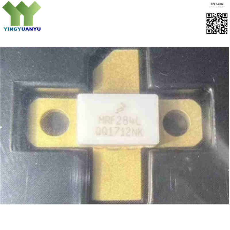
MRF284L
| Part Number | MRF284L (MRF284LR1, MRF284LSR1) |
|---|---|
| Manufacturer | NXP Semiconductors / Freescale |
| Category | Discrete Semiconductor Products > Transistors – FETs, MOSFETs – RF |
| Description | RF Power LDMOS N‑Channel Field‑Effect Transistor, 135W PEP, 30W CW, 28V, up to 2000MHz. |
| Stock Status | In Stock |
| Origin | Original Factory |
Product Overview
The MRF284L is a high‑performance N‑channel broadband LDMOS RF power FET for wideband power amplifiers up to 2600 MHz. Built with advanced LDMOS technology, it delivers high output power, excellent linearity and strong load‑mismatch robustness. Powered by 28 V drain supply, it fits cellular base stations, wireless infrastructure, ISM generators and broadcast amplifiers. It supports 135 W PEP peak power and 30 W CW continuous power under different test conditions.
Core Advantages
High Output Power & Gain
Delivers 135 W PEP peak and 30 W CW continuous power with high gain across 1.0‑2.0 GHz, reducing amplifier stage count.
Superior Linearity & Efficiency
Low IMD distortion and high drain efficiency, ideal for modern digital wireless modulation schemes.
High Ruggedness & VSWR Tolerance
Withstands 10:1 VSWR mismatch without damage, suitable for harsh real‑world RF environments.
Low‑Thermal‑Resistance Package
Flanged hermetic package enables efficient heat dissipation for high‑power CW or pulsed operation.
Key Specifications
| Brand | NXP Semiconductors / Freescale |
|---|---|
| RoHS Status | RoHS Compliant / Lead‑Free Options Available |
| EDA / CAD | PCB Footprint & 3D Model Available upon Request |
| Warranty | 1‑Year Standard Quality Warranty |
| Package / Case | NI‑780 / Flanged Hermetic RF Package (Case 360B‑05) |
| Mounting Type | Chassis Mount / Flange Mount |
| Surface Marking / Silkscreen | MRF284L Marking |
| Transistor Type | LDMOS N‑Channel RF Power MOSFET |
| Frequency Range | 1000 MHz ~ 2600 MHz (Recommended operating up to 2000 MHz) |
| Output Power (Pout) | 135 W PEP Peak; 30 W CW Continuous (@2.0 GHz) |
| Drain‑Source Voltage (Vdss) | 65 V (Max) |
| Gate‑Source Voltage (Vgs) | ±20 V (Max) |
| Operating Drain Supply Voltage (Vdd) | 28 V (Typ); 26 V (Test condition for 30W CW) |
| Power Gain (Gps) | ~12.5 dB (PEP) / 9.5 dB (CW) @ 2.0 GHz |
| Total Device Dissipation (Pd) | 87.5 W (@25°C) |
| Thermal Resistance, Junction‑to‑Case (RθJC) | 2.0 °C/W |
| Operating Junction Temperature | -65°C to +200°C |
| Storage Temperature Range | -65°C to +150°C |
Typical Applications
- Cellular Base Station Transmitters (GSM, EDGE, WCDMA, LTE)
- Wireless Infrastructure Broadband Power Amplifiers
- Industrial, Scientific, and Medical (ISM) RF Power Generators
- Avionics, Radar Systems, and Commercial Communication Repeaters
- TV/FM Digital Broadcast Power Amplifier Stages
Order & Shipping Info
| Minimum Order Quantity (MOQ) | 1 Piece |
|---|---|
| Shipping Time | Shipped within 1‑2 business days |
| Delivery Time | 3‑7 working days worldwide |
| Shipping Methods | DHL, UPS, FedEx, EMS |
| Payment Methods | T/T (Bank Transfer), PayPal, Credit Card, Western Union |
Technical Support
For datasheet, sample requests, stock check, or bulk pricing, please use the Quick Inquiry form. We will reply within 24 hours.
Frequently Asked Questions
Q1: What operating frequency range does the MRF284L support?
A: The MRF284L covers 1000‑2600 MHz for broadband RF applications. Practical recommended operation is up to 2000 MHz (2.0 GHz).
Q2: What is the difference between 135W and 30W output power for MRF284L?
A: 135 W is PEP peak power for two‑tone test; 30 W is CW continuous power for single‑tone test. Both are valid specs for the same device under different test conditions.
Q3: What is the difference between MRF284L, MRF284LR1 and MRF284LSR1 suffix variants?
A: MRF284L is the base part number. MRF284LR1 / MRF284LSR1 are tape‑and‑reel packaging variants. Die, package and electrical performance are identical; only packaging format differs.
Q4: What package style is used for MRF284L?
A: It adopts NI‑780 / Case 360B‑05 flanged hermetic RF package for chassis heat‑sink mounting. Junction‑to‑case thermal resistance is 2.0 °C/W.
Q5: Can MRF284L withstand high VSWR load mismatch?
A: Yes. It can handle up to 10:1 VSWR mismatch at rated output power, suitable for harsh real‑world RF amplifier environments.
Q6: Are there compatible or replacement alternatives for MRF284L?
A: Direct pin‑to‑pin compatible alternatives: MRF284LR1, MRF284LSR1. For higher‑power upgrades, please contact us for custom selection. Always verify operating voltage and frequency range for substitute parts.
Q7: What precautions should be taken for MRF284L assembly and handling?
A: MRF284L is an MOS device sensitive to ESD. Use anti‑static handling. Ensure good thermal interface between flange and heat sink to keep junction temperature below 200°C maximum rating.
Q8: How can I request RF datasheets, s‑parameter files, or volume pricing for MRF284L?
A: Official datasheets, S‑parameter simulation models, stock status and bulk price quotes can be submitted directly via our Quick Inquiry form.
Related Products

