
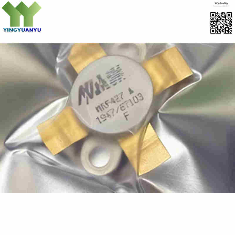
MRF427
| Part Number | MRF427 |
|---|---|
| Manufacturer | Motorola / NXP / ASI |
| Category | Discrete Semiconductor Products > Transistors > Bipolar RF Transistors |
| Description | NPN Silicon RF Power Transistor, 30W PEP Output, DC‑30 MHz HF Band, 28V Operation, Excellent IMD Linear Performance. |
| Stock Status | In Stock |
| Origin | Original / Authorized Substitute |
Product Overview
MRF427 is NPN silicon RF power BJT for DC‑30 MHz HF linear amplifiers. Originally from Motorola‑NXP, ASI also provides cross‑brand compatible units. Operating at 28 V DC, it delivers 30 W PEP with low IMD3 distortion. Built‑in emitter ballast resistors improve VSWR ruggedness. Hermetic FM‑4 flange‑mount package for military, marine and ham radio transmitters. Note: NXP original and ASI versions have different maximum junction temperature ratings.
Core Advantages
Superior Linear & Low IMD Performance
Tuned for Class A/AB/B SSB amplifiers, IMD3 ≤‑34 dBc for clean HF signal output.
High VSWR Ruggedness
Internal emitter ballast resistors prevent thermal runaway under severe antenna mismatch.
Hermetic Metal‑Ceramic Package
Gold‑metallized FM‑4 flange package, stable and reliable for harsh radio environments.
28V Standard Rail Compatibility
Matches common 28 V power supply for fixed and vehicle‑mount HF transmitting equipment.
Key Specifications
| Brand | Motorola / NXP / ASI |
|---|---|
| RoHS Status | RoHS Compliant options available / Leaded Industrial Standard |
| EDA/CAD | Symbol, Footprint & 3D Model Available |
| Warranty | 1‑Year Standard Quality Warranty |
| Package / Case | FM‑4 / O‑CRFM‑F4, 0.500‑Inch Flange‑Mount, Hermetic 4‑Pin Metal‑Ceramic Package |
| Mounting Type | Chassis Mount / Through‑Hole Flange Mount |
| Surface Marking / Silkscreen | MRF427 Marking |
| Transistor Polarity | NPN Silicon RF Bipolar Transistor (BJT) |
| Frequency Range | DC to 30 MHz (HF Band) |
| Output Power | 30 W PEP (Peak Envelope Power) |
| Supply Voltage | 28 V DC Nominal |
| Collector‑Emitter Voltage (Vceo) | 65 V DC Max |
| Collector‑Base Voltage (Vcbo) | 110 V DC Max |
| Maximum Collector Current | 6 A DC Max |
| Maximum Power Dissipation | 80 W @ 25°C Case Temperature |
| Power Gain | Typ. ≥18 dB (25 W Output, 30 MHz, 28 V) |
| DC Current Gain (hFE) | Minimum 15 (under specified test condition) |
| Thermal Resistance θJC | Approx. 2.19 °C/W (Junction‑to‑Case) |
| Third‑Order IMD Performance | IMD3 ≤ ‑34 dBc @ 25 W Output |
| Operating Junction Temperature | -65°C ~ +150°C (NXP‑Motorola original);‑65°C ~ +200°C (ASI version) |
| Packaging Format | Tray / Anti‑Static Protective Box Packaging |
Typical Applications
- High‑frequency (HF) Single Sideband (SSB) linear power amplifier stages
- Military and tactical HF communication transceivers (DC‑30 MHz)
- Marine HF radio communication systems and coastal station transmitters
- Amateur radio (Ham Radio) high‑power linear amplifiers
- Commercial fixed‑station and mobile HF radio power drivers
Order & Shipping Info
| Minimum Order Quantity (MOQ) | 1 Piece |
|---|---|
| Shipping Time | Shipped within 1‑2 business days |
| Delivery Time | 3‑7 working days worldwide |
| Shipping Methods | DHL, UPS, FedEx, EMS |
| Payment Methods | T/T (Bank Transfer), PayPal, Credit Card, Western Union |
Technical Support
For datasheet, sample requests, stock check, or bulk pricing, please use the Quick Inquiry form. We will reply within 24 hours.
Frequently Asked Questions
Q1: What is the primary operating frequency band for the MRF427?
A: It covers DC‑30 MHz full HF band, optimized for SSB linear transmitters under 28 V supply.
Q2: What is the difference between NXP‑Motorola original and ASI cross‑brand MRF427?
A: Main electrical parameters match. NXP original max junction temperature is +150°C; ASI upgraded version reaches +200°C. Always follow the corresponding manufacturer datasheet for thermal design.
Q3: Can MRF427 directly replace MRF428?
A: They share identical FM‑4 package and pinout. MRF428 delivers higher output power. Physically pin‑compatible, but bias circuit and heatsink must be readjusted, not true plug‑and‑play swap.
Q4: Are there cross‑brand or drop‑in competitor alternatives for MRF427?
A: ASI MRF427 is the main cross‑brand substitute. No full drop‑in equivalent from other vendors. Similar‑power HF transistors still require input‑output impedance re‑matching even with same package.
Q5: Why is Vcbo (110V) much higher than Vceo (65V)?
A: Vcbo is collector‑base voltage with emitter open. Vceo is real‑world working collector‑emitter rating. Do not exceed 65 V on collector‑emitter in practical circuits to avoid device damage.
Q6: Does the same flange‑mount package guarantee pin‑to‑pin compatibility?
A: No. Same flange dimension does not mean identical pin assignment. Always double‑check pin‑out before soldering to prevent transistor burnout.
Q7: What thermal requirements apply to MRF427?
A: Junction‑to‑case thermal resistance θJC ≈2.19°C/W. Firm thermal contact to heatsink is mandatory. Derate output power if operating near maximum junction temperature.
Q8: Can MRF427 be used for AM broadcast transmitter?
A: Yes, it supports AM mode. Note that AM applications have higher thermal stress, sufficient heatsink and power derating are strongly recommended.
Q9: How can I get datasheet, reference circuit or bulk quotation?
A: Please submit your demand via quick inquiry form. Our team will send datasheet, stock confirmation and pricing within 24 hours.
Related Products

